
Widespread orientation measurement of fractures offers several significant benefits across the mining value chain, ranging from geological understanding to geotechnical assessments and mining efficiency.
Dependent Models
The outputs of the following models are used:
|
Model Name |
Model Type |
|
Fracture Detection and Classification |
Object Detection |
|
Drillers Break |
Object Detection |
|
Fracture Mask |
Instance Segmentation |
|
Orientation Line Tick |
Object Detection |
Data Processing
The following steps are taken to determine the orientation of a given fracture. This process is completed on every fracture we can measure.
-
Take the output of the fracture detection model, “simple” classes only
-
Run a segmentation model to extract the fracture profile

- Prediction of the orientation line proceeds with detection of the orientation tick marks on the core

- Combine the fracture profiles and the orientation line ticks

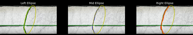
- Fit ellipses to the left, middle and right of the fracture interface, undertake QA to determine which measurements are suitable
- Using survey line, determine the dip and dip direction of the fracture.
Product Configuration Options
|
Configuration |
Options |
|
Location of ori line as marked by the orientation tool |
Bottom (default); or Top of core |
|
Positive dip direction as measured by the survey tool |
Down/below horizontal (default); or Up/above horizontal |
User Data
Downhole survey data must be provided in the following format format:
-
HoleID_survey.csv
CSV file to contain the following headers:
|
File Header |
Description |
|
depth |
The vertical distance from the surface down to the bottom of the drilled hole |
|
azimuth |
Azimuth is the horizontal orientation of the drill path, measured in degrees from true north (or grid north). |
|
dip |
Dip refers to the angle at which the drill hole deviates vertically from the horizontal plane, measured in degrees. |
Data Output
Development is currently underway to enable viewing predictions in Datarock Core.
Results from this model can be obtained using the Downloads dropdown list:

The available CSV files include the following:
-
ProjectName_fracture_orientation.csv
This output includes a list of every detected fracture in the hole, with orientation measurements included, or reason for not successfully measuring.
|
File Header |
Description |
|
hole_id |
Customer’s Hole ID |
|
depth_m |
Depth of fracture downhole (metres) |
|
depth_ft* |
Depth of fracture downhole (feet) |
|
fracture_azimuth |
Fracture azimuth angle |
|
fracture_dip |
Fracture dip angle |
|
ori_tick_count |
Orientation tick marks associated with the ori line detection for that fracture |
|
has_data |
Includes Y or N based on whether orientation measurements have been made. Provides transparency on whether it has been measured, enabling quicker data reviews and filtering for database import if required. |
|
no_data_reason |
Provides a reason if orientation measurements aren't made e.g. "No orientation line detected". |
|
pipeline_version |
Version of the processing pipeline that creates the product data. |
*Only included if project depths are in feet.
Product Limitations
|
Limitation |
Comment |
|
Image Quality and Resolution |
Like all Datarock products, the accuracy of fracture orientation measurements rely on well presented and photographed drill core. Poor core markup and curation, as well as poor quality imaging can limit the quality of the outputs. |
|
Core Surface Conditions |
Drilled cores can have irregular surfaces, cracks, or fragmented areas. These conditions can obscure or mimic tick marks, leading to false detections or missed fracture measurements. |
|
Orientation Tick Mark Clarity |
Orientation line tick marks made during the core markup process may not always be clear or consistent. If the tick marks are faint, worn off or partially damaged, the models model may be limited in their ability to detect them. |
|
Overlap with Other Markings |
Other types of markings on the core, such as geological annotations and cut lines, can be mistaken for orientation lines if not clearly differentiated. We recommend following Datarock’s Core Photography Guidelines for best practice (contact us for details). |
|
Fractures parallel to core axis |
Fractures that are parallel to the core axis are generally not measured due to the way they are normally presented within the image. |
|
Difference between Datarock and logged data |
Datarock will measure and provide data for every measurable fracture, whereas manually logged data will include selected measurements only. |
Document Version
|
Version |
Date |
Author |
Rationale |
|
1 |
10 Jan 2024 |
L Yanez |
Initial release |
|
2 |
29 Jan 2024 |
S Johnson |
Updated to include depth in feet |
|
3 |
15 Jan 2025 |
S Johnson |
Updated to include additional fields in outputs. |
|
4 |
12 May 2026 |
R Duyvestyn |
Update outputs |